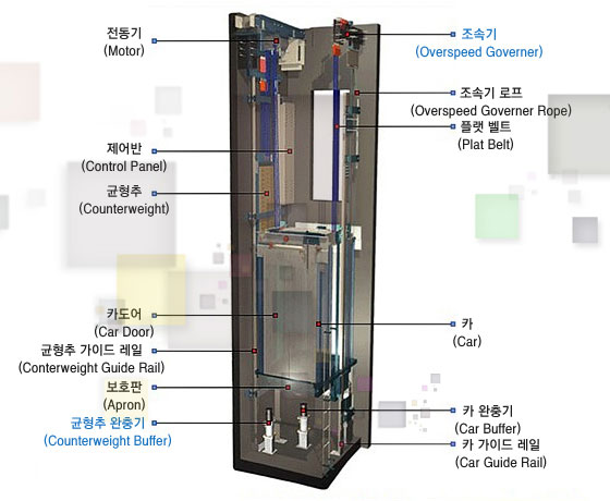
일반 로프식 엘리베이너는 권상기, 제어반 및 조속기 등의 부품을 설치 할 승강로 상부의 기계실이 필수적이었으나 첨단의 기술로 핵심부품을 콤팩트화하여 한 승강로 안에 모든 시스템을 설치하는 혁신을 이루었습니다. MRL엘리베이터의 권상기는 감속기가 필요없는 무기어형(Gearless)의 영구 자석형 동기모터를 채용하였으며, 주요부품을 승강로 하부 핏트부보다 높게 설치하여 침수와 화재에 대비 하였습니다. MRL엘리베이터의 제어반은 콤팩트화 되어있어 최하층 승강장 출입구면에 설치되며 동기모터제어 전용의 인버터를 적용하여 최적의 상태로 엘리베이터를 제어합니다.
| 기계실 없는 승강기(Machine Roomless) 구조도 | |
|---|---|
 |
 |
|
|
동기모터형 권상기와 일반형 권상기 비교
| 구분 | 동기모터형 권상기 | 일반형 권상기 |
|---|---|---|
| Gear방식 | 무기어방형(Gearless) | 감속기어형(Geared) |
| 전동기 | 영구자석형 동기 전동기 | 삼상 유도 전동기 |
| 전력소모율 | 매우 좋음(일반형의 약70% 소비) | 보통 |
| 장점 | 저소음, 고효율, 오일 불필요, 저렴한 보수 비용 | 상대적으로 저렴한 가격 |
| 적용기준 | MRL 엘리베이터, MMR(미니 기계실)엘리베이터 | 상부 기계실형 로프식 승강기 |
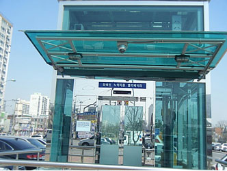
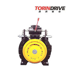
| MRL용 동기모터 | 제어반층 출입구 디자인 |
|---|---|
 |
 |
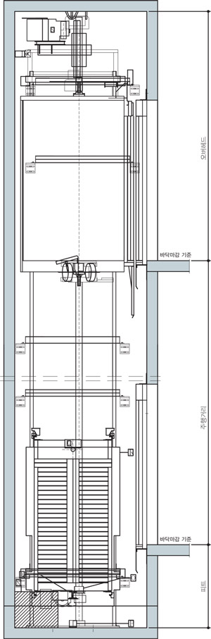
| OVERHEAD 단면도 | 승강로 단면도 |
|---|---|
 |
 |
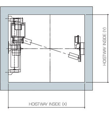
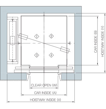
| OVERHEAD 평면도 | |
 |
|
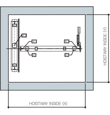
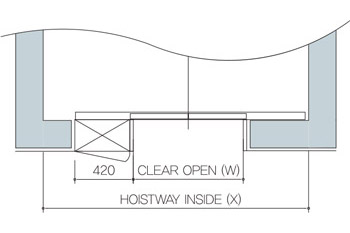
| PIT 평면도 | |
 |
| 표준 규격 (최소 규격) & 전원 용량 | ||||||||
|---|---|---|---|---|---|---|---|---|
| 속도 | 인승 | 적재하중 | 출입문 규격 | 카 내부 규격 | 승강로 내부 규격 | 모터용량 | MCCB 용량 | HOOK |
| (m/s) | (Kg) | (mm) | (AxB)(mm) | (XxY)(mm) | (kW) | 작용하중 | ||
| 1.0 | 4 | 320 | 700x2100 | 850x1000 | 1600x1300 | 2.8 | 20A | 1500kg |
| 4 (SIDE OPEN) | 1400x1400 | |||||||
| 6 | 450 | 800x2100 | 1000x1200 | 1750x1500 | 4 | |||
| 8 | 550 | 800x2100 | 1100x1250 | 1800x1550 | ||||
| 9 | 630 | 800x2100 | 1100x1400 | 1800x1700 | 3000kg | |||
| 11 | 750 | 800x2100 | 1300x1400 | 1930x1700 | 6.3 | |||
| 13 | 900 | 900x2100 | 1600x1350 | 2200x1650 | ||||
| 15 | 1000 | 900x2100 | 1600x1400 | 2200x1700 | ||||
| 1.5 | 8 | 550 | 800x2100 | 1100x1250 | 1800x1560 | 6 | 40A | 1500kg |
| 9 | 630 | 800x2100 | 1100x1400 | 1800x1710 | 3000kg | |||
| 11 | 750 | 800x2100 | 1300x1400 | 1930x1710 | 9.5 | |||
| 13 | 900 | 900x2100 | 1600x1350 | 2200x1660 | ||||
| 15 | 1000 | 900x2100 | 1600x1400 | 2200x1710 | ||||
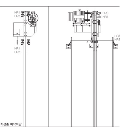
| 머신빔 반력값 & PIT 반력값 | |||||||||
|---|---|---|---|---|---|---|---|---|---|
| 적재하중 (kg) |
Gov축 하중 (벽 수평하중) |
Gov축 하중 (벽 수평하중) |
Gov축 하중 (벽 수평하중) |
Gov축 하중 (벽 수평하중) |
카축 Buffer 충격하중 |
CWT축 Buffer 충격하중 |
카축 비상정지시 충격하중 |
가이드슈 반력 |
가이드슈 반력 |
| HR1 | HR2 | HR3 | HR4 | R1 | R2 | R3 | Fx | Fy | |
| 320 | 650 | 300 | 1250 | 750 | 2070 | 3380 | 3250 | 88 | 90 |
| 450 | 2430 | 3820 | 3670 | ||||||
| 550 | 2630 | 4000 | 3890 | ||||||
| 630 | 2950 | 4460 | 4330 | ||||||
| 750 | 3530 | 5360 | 5250 | 175 | 225 | ||||
| 900 | 4400 | 6740 | 6300 | ||||||
| 1000 | 4630 | 7000 | 6640 | ||||||
| OVERHEAD & PIT | ||
|---|---|---|
| 속도 (m/s) | 오버헤드 (mm) | 피트 (mm) |
| 1.0 | 3450 / 3800 | 1150 |
| 1.5 | 3800 | 1500 |
* 에어컨 설치 시 당사 영업팀에 문의바랍니다. (속도 1.5m/s일 경우 해당)
| 승강로 평면도 | 최상층 삼방틀 상세도 |
|---|---|
 |
 |
For general rope-type elevators, the machine room at the upper part of the hoistway to install parts such as a traction machine, control panel, and speed regulator was required. However, innovation that installs every system in one hoistway by miniaturizing core parts with the latest technology. The traction machine of the MRL elevator adopts the gearless permanent magnetic synchronous motor not requiring a speed regulator. As main parts are installed higher than the fir part of the lower part of the hoistway, it is protected from flooding and fire. The control panel of the MRL elevator is made compact so it is installed on the exit/entrance side of the platform on the lowest floor. It also controls the elevator in optimum status as it adopts the inverter exclusive for synchronous motor control.
| Machine Roomless structure chart | |
|---|---|
|
|
|
|
Comparison of the synchronous motor type traction machine and general traction machine
| Distinction | synchronous motor type traction machine | general traction machine |
|---|---|---|
| Gear | Gearless | Geared |
| Motor | permanent magnetic synchronous motor | three-phase induction motor |
| Power consumption rate | Very good (consumes about 70% of the general type) | Fair |
| Advantages | Low noise/high efficiency/oil not-required/inexpensive maintenance expenses | Relatively inexpensive price |
| Application standards | MRL elevator, MMR(mini machine room) elevator | Top machine room type rope-type elevator |
| Synchronous motor for MRL | Control panel floor exit/entrance design |
|---|---|
|
|
| Cross-sectional drawing of the OVERHEAD | Cross-sectional drawing of the hoistway |
|---|---|
|
|
| Floor plan of the OVERHEAD | |
|
|
| Floor plan of the PIT | |
|
| The Standard (Minimum Standard) & Power Capacity | ||||||||
|---|---|---|---|---|---|---|---|---|
| Speed | For Passengers | Live load | Entrance Standard | Entrance Standard | Interior Standard of Elevator Hoist-way | motor capacity | MCCB capacity | HOOK |
| (m/s) | (Kg) | (mm) | (AxB)(mm) | (XxY)(mm) | (kW) | Applied Load | ||
| 1.0 | 4 | 320 | 700x2100 | 850x1000 | 1600x1300 | 2.8 | 20A | 1500kg |
| 4 (SIDE OPEN) | 1400x1400 | |||||||
| 6 | 450 | 800x2100 | 1000x1200 | 1750x1500 | 4 | |||
| 8 | 550 | 800x2100 | 1100x1250 | 1800x1550 | ||||
| 9 | 630 | 800x2100 | 1100x1400 | 1800x1700 | 3000kg | |||
| 11 | 750 | 800x2100 | 1300x1400 | 1930x1700 | 6.3 | |||
| 13 | 900 | 900x2100 | 1600x1350 | 2200x1650 | ||||
| 15 | 1000 | 900x2100 | 1600x1400 | 2200x1700 | ||||
| 1.5 | 8 | 550 | 800x2100 | 1100x1250 | 1800x1560 | 6 | 40A | 1500kg |
| 9 | 630 | 800x2100 | 1100x1400 | 1800x1710 | 3000kg | |||
| 11 | 750 | 800x2100 | 1300x1400 | 1930x1710 | 9.5 | |||
| 13 | 900 | 900x2100 | 1600x1350 | 2200x1660 | ||||
| 15 | 1000 | 900x2100 | 1600x1400 | 2200x1710 | ||||
| Machine Beam Reaction Force & PIT Reaction Force | |||||||||
|---|---|---|---|---|---|---|---|---|---|
| Live load (kg) |
Governor Shaft Load (Horizontal Load of the Wall) |
Governor Shaft Load (Horizontal Load of the Wall) |
Governor Shaft Load (Horizontal Load of the Wall) |
Governor Shaft Load (Horizontal Load of the Wall) |
Buffer Impact Load of the Car Shaft | Buffer Impact Load of CWT Shaft | Impact Load at the time of Car Shaft Emergency Shutdown | Guide Shoe Reaction Force | Guide Shoe Reaction Force |
| HR1 | HR2 | HR3 | HR4 | R1 | R2 | R3 | Fx | Fy | |
| 320 | 650 | 300 | 1250 | 750 | 2070 | 3380 | 3250 | 88 | 90 |
| 450 | 2430 | 3820 | 3670 | ||||||
| 550 | 2630 | 4000 | 3890 | ||||||
| 630 | 2950 | 4460 | 4330 | ||||||
| 750 | 3530 | 5360 | 5250 | 175 | 225 | ||||
| 900 | 4400 | 6740 | 6300 | ||||||
| 1000 | 4630 | 7000 | 6640 | ||||||
| OVERHEAD & PIT | ||
|---|---|---|
| Speed (m/s) | Overhead (mm) | Pit (mm) |
| 1.0 | 3450 / 3800 | 1150 |
| 1.5 | 3800 | 1500 |
* Please contact our Business Team when installing the air conditioner. (Applicable to a speed of 1.5m/s)
| Floor plan of the hoistway | Detail Drawing of the Top Floor Jamb |
|---|---|
|
|